
What Hardware Components Are Inside a BMS?

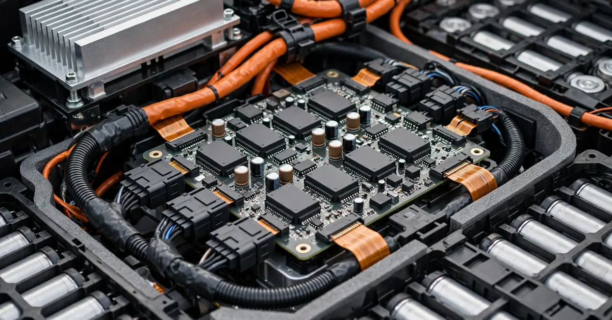
A BMS contains an analog front-end for sensing, a microcontroller for processing, power electronics like MOSFETs and contactors for control, and communication interfaces for reporting data, all working together as one tightly integrated control loop. Each piece plays a distinct role, and understanding them individually makes it much easier to understand how the whole system actually functions.
The Analog Front-End (AFE): Where Sensing Happens
The AFE is the chip closest to the battery itself, directly reading cell voltage, temperature, and often current. It contains high-resolution ADCs to convert those analog signals into precise digital readings the rest of the system can use. Because the AFE sits physically closest to the cells, many designs let it control protection circuitry directly, reacting to a fault faster than routing everything through the microcontroller first.
The Microcontroller Unit (MCU): Where Decisions Happen
The MCU is the central processor running the BMS’s core algorithms, state-of-charge and state-of-health estimation, balancing logic, and fault management. It takes data from the AFE and any fuel gauge IC, then decides what actions the rest of the hardware needs to take. More complex analysis, like impedance tracking, demands more processing power, which is why MCU selection is a major design decision.
The Fuel Gauge IC: Where SOC/SOH Calculation Often Lives
In many designs, a dedicated fuel gauge IC, sometimes standalone, sometimes embedded within the MCU, uses cell modeling and estimation algorithms specifically to calculate state of charge and state of health, offloading that specialized computational work from the general-purpose MCU.
Power Electronics: Where Control Actually Happens
MOSFETs and Gate Drivers
MOSFETs handle load switching, contactor control, and balancing functions, with gate drivers providing the isolated signals needed to switch them reliably.
Contactors, Relays, and Fuses
These provide the actual physical disconnect capability, contactors and relays for electronically controlled disconnection, fuses as a mechanical backup layer that operates independently of any software decision.
Protection Circuitry
Components like TVS diodes protect the circuit board itself from voltage transients, particularly important during high-current switching events.
Sensors: The Data Source for Everything Else
Beyond the AFE’s voltage sensing, dedicated current sensors (shunts or Hall-effect devices) and temperature sensors (typically NTC thermistors) feed the raw measurements that every other BMS function depends on.
Communication Interfaces
Internally, interfaces like isoSPI connect the AFE chain to the MCU across isolation barriers in multi-cell stacks. Externally, isolated CAN, LIN, or increasingly Ethernet connect the BMS to the vehicle’s broader control systems, chargers, and diagnostic tools.
Memory and Passive Components
Memory stores calibration data, fault logs, and firmware. Passive components, resistors, capacitors, and PCB traces themselves, round out the physical circuit, with careful layout required to manage noise immunity and high-voltage isolation across the board.
| Component | Primary Role |
|---|---|
| Analog front-end (AFE) | Cell voltage/temperature sensing, fast local protection |
| Microcontroller (MCU) | Runs core algorithms and decision-making |
| Fuel gauge IC | Specialized SOC/SOH calculation |
| MOSFETs/contactors/fuses | Physical load switching and disconnection |
| Communication interfaces | Internal (isoSPI) and external (CAN/LIN) data flow |
Conclusion
A BMS is built from a coordinated set of hardware components: an analog front-end for precise sensing, a microcontroller for decision-making, power electronics for physical control, and communication interfaces tying it all to the rest of the vehicle. Each piece is specialized for its specific role, and it’s the tight integration between them that makes real-time battery protection and management possible.
FAQs
What’s the difference between the AFE and the MCU?
The AFE handles direct sensing and can react to faults immediately; the MCU runs the more complex algorithms and overall decision-making.
Why do some BMS designs let the AFE control protection directly instead of the MCU?
It provides a faster response time and reduces the complexity and resource demand placed on the MCU’s firmware.
Are fuses still necessary if the BMS has electronic contactor control?
Yes, fuses serve as an independent, purely mechanical backup layer in case the electronic response is delayed or fails.
